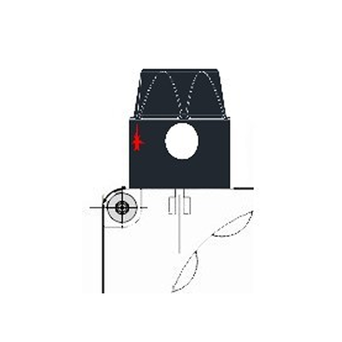
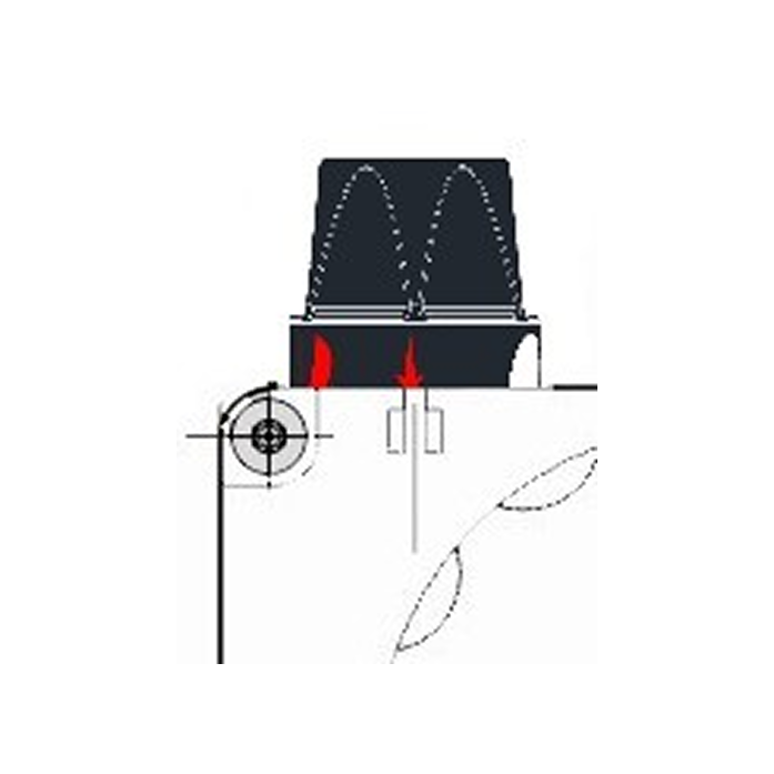
Depress and turn the control knob to the pilot position![]()
Depress the button and ignite the pilot flame while
keeping the knob fully depressed for a few seconds .
Release the knob and check that the pilot flame stays
lit. If it goes out, repeat the ignition operation.
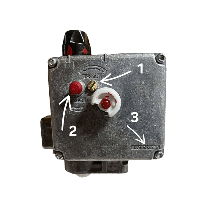
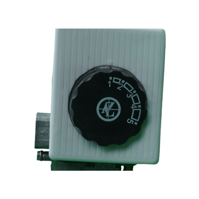
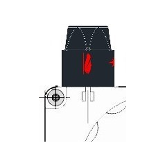
Depress and turn the control knob to the position
corresponding to symbol ![]() . On release, the knob
. On release, the knob
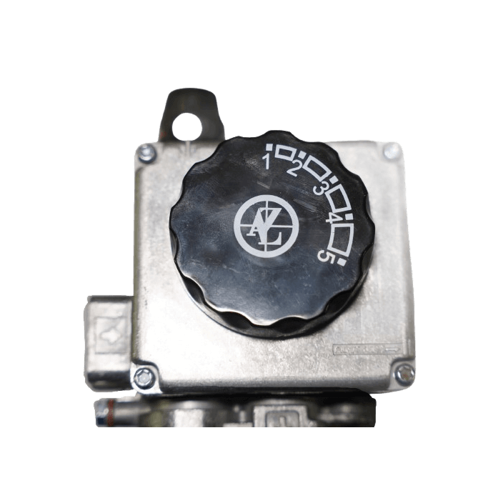
returns to the ON position ![]() . Turn the temperature
. Turn the temperature
selection knob to the point corresponding to the
desired temperature .
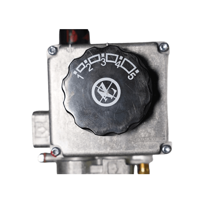
To close the main burner and keep the pilot flame on,
depress and turn the control knob to the pilot position ![]() .
.

Turn the control knob to the OFF position ![]() .
.
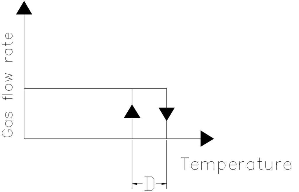
CAUTION: after shutting down, wait at least two
minutes before re-igniting so as to allow the flame
failure device to return to the safety position.